Tine Eie
Member of powertrain department
Managing: Engine
The engine is the very heart of the vehicle, being the sole power source in most cases. Hence its functionality is critical for the car. The choice of engine is the same for AR20 as for AR19, namely the KTM 690 single cylinder engine.
Front engine mounts

Concept and design
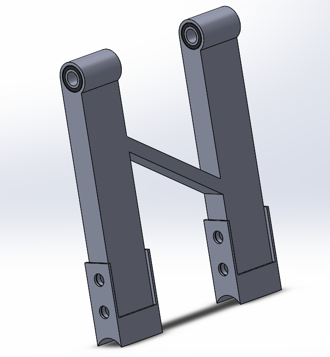
The front engine mounts consists of two main parts; an alu part which is directly fastened to the engine, and a steel bracket which is welded to the frame. The alu fasteners are reinforced with a square tube in between. Setting the concept for the mounts, the prime factor to consider was the fact that the engine would be lowered out of the car for AR20, as opposed to the solution for AR19 which included pulling it out from behind with the rear bulkhead. Therefore, the most significant change of design is the length of the brackets as they would intersect the engine otherwise. Another important difference is the bracket walls. They are designed with the intention of managing to extract the alu fasteners from the front. This allows the mounts to be removed with only a slight elevation of the engine as the alu fasteners clear the front bracket wall (~5mm).
Choice of materials
As mentioned in the previous section, two main parts comprise the mounts. The choice of steel for the brackets was a no-brainer, as they would be welded to the frame which, naturally, is made of steel. Choosing alu for the main fasteners was relatively easy to decide, although not a matter of course. The main reason for replacing steel with alu is weight reduction. Still, the engine mounts are rarely the components one chooses to cut weight on as their main purpose (and quite crucial) is holding the engine. But we made the decision that aluminium would be adequate for its mission, and for a greater sense of safety, the walls are relatively thick. The alloy used is 6082 as this is fairly sturdy for aluminium. 7075 is notably stronger, but lack the welding friendliness.
Production and challenges
Starting to produce the mounts went relatively smoothly when considering the alu fasteners. A square tube was ordered and with a bit of cutting and milling the alu part was finished. The steel brackets on the other hand became more complicated. Originally, the plan for them was also machining them from a square tube. Unfortunately the access to the measurements was quite limited and a bulk had to be bought, which would be a quite significant expense, not to mention, unnecessary. So the conclusion was to make them from steel plates. There are quite a few downsides to this method. First of all, by welding at several places (in this case all four corners), one weakens the material significantly. Secondly, it is a lot more difficult to make them precise. Also, it simply takes more time. Naturally this was not the desired solution, but merely a method that works although not much more.
Rear engine mount assembly

Concept and design
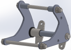
The rear engine mount assembly consists of 3 different parts bolted to the engine’s two existing bolt holes, the latter originally being used to mount the engine to the KTM motorbikes. We are not fortunate enough to have a narrow frame, which could easily have let us mount the engine in the traditional way (as in original KTM bikes). In this design we could have used the engine as a structural part of the chassis. Instead we utilize the car’s backplate to mount it. As seen on the 3D model, we used brackets with polyurethane bushings to dampen the engine’s vibrations into the chassis. This whole assembly is being held together by a hollow alu shaft which is intersected by a bolt to tighten the brackets, bushings and side plate/arms. Those two 10mm hols in the side plates are meant for clicktronic mounting.
Choice of materials
This assembly consists of many different materials. The arms/side plates are made of 7075 T6 alu for its supurb strength and its weight. Poly bushings are purchase at Powerflex Germany or UK and consist of 80 shore A, an alternative can be the 70 shore A. The bushing brackets are made of normal steel for its weld properties and its strength. This bracket is welded together by 3 different parts: bushing tube, square standoff tube, and plasma cut bolt flange. These are the critical material copies, the other bones are just what we had at hand.
Production and challenges
Production went relatively painless. I had some difficulties finding the right rectangle tubing for my standoffs which are one of the welded parts in the bushing brackets. I solved this issue by cutting down a square tube and then welding it together again. The other issue was that one of those bushing tubes got a bit egg-shaped when fitting it in the 4 jaw lathe, but I kept a lot of safety margin in the material because I knew that welding would cause some geometric issues. Especially warping of its bolting flange, which I prevented by putting it in a hydraulic press directly after welding (it was still red) and straining it by eye.
