Ørjan Øvsthus
Member of chassis department
Managing: Primary structure
The frame, aka. Chassis, is the biggest single component of the car. It is the main structural member of the car, where all the other components are attached. As an engine could be called the heart of the car, a frame could be called the skeleton of the car.
This years frame is based upon the bachelors thesis “Optimization of a Formula SAE Space Frame”, made by 4 members from the AR19 team. Some adjustments were made to the design, but it remained mostly similar.
Concept
The thesis studied four different concept
(1) Weight reduction
(2) Torsional stiffness
(3) Round vs square tubes
(4) Focus on suspension/different geometry
Concept (4) was chosen due to the desire to place all loads from suspenstion in nodal points.
Not the lightest nor stiffest concept, but a great combination of all four and a key factor was the placement of nodal points with repsect to the suspension.
Design
The original plan was to introduce a pushrod front suspension system with AR20, so some modifications were made to the frame in order to make this possible. We also altered the front bulkhead in due to FS-rules considering the Front Wing (max 700mm from front tire to front-end of the front wing). The pushrod suspension would impair the view of the driver, so it was scrapped. Pushrod suspension is achievable, but it would need modifications to the front bulkhead support. We also reverted the changes to the bulkhead, as FS-rules would not allow the modifications made, and we managed to fit the front wing with a design more close to the one from the bachelors thesis.
Original Design
The original design included a K-shaped cross on top of the “front bulkhead support”, in order to support the front suspension system including an ARB(Anti-Roll Bar). This meant that the rockers would have to be placed on top of the “front bulkhead support” and with the current frame design, this would impair the driver’s vision. Therefore, the decision was made to change the suspension system which meant that we could remove the “K-cross”.
The changes to the front bulkhead included an “upward bend” on the lower support member 150mm behind the front bulkhead. This bend was made to fit part of the front wing under the frame. FS-Rule T 3.14.1, regarding the front bulhead support, states that “the lower support member must be attached to the base of the front bulkhead and the base of the front hoop”. The rules does not mention anything about the tube having to be straight, but after consulting with some FSAE judges, we had to revert the change as they did not approve of the design. Luckily, with some changes to the lengths of different parts of the car, we were able to fit the wing to a design closer to the one from the bachelor’s thesis
Final design
The final design of the frame ended up being quite similar to the bachelor’s thesis. Changes include: Raising the lower support members of the rear bulkhead, lowering and widening node-point on the sidewalls of the front bulkhead support, small adjustments to the heights of the hoops and the front bulkhead, ect.
Final design
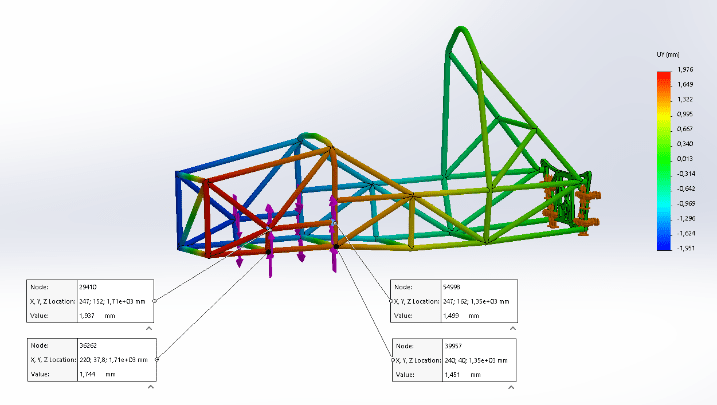
We ran an “Finite Element Method” (FEM) analysis on the final design to ensure that the frame’s torsional stiffness was above our requirement of 600Nm/deg. The analysis was performed using Solidworks 2019, on an assembly with the AR20 Space frame and AR20_C05_RearBulkhead.
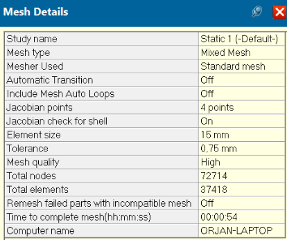
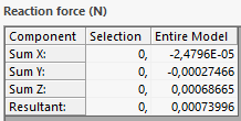
The FEM analysis is based off of the bachelor’s thesis: “Optimization of a Formula SAE Space Frame”. For the mesh, we used the same parameters as in the bachelor’s thesis: 15mm, with 0.75mm tolerance. The assembly was held at the rear bulkhead suspension points and a force of 250N was applied at the front suspension points.


The torsional stiffness was calculated by finding the average torque, and average torsional angle of the front suspension points and then dividing the torque by the angle. The results showed a torsional stiffness of 1202[Nm/deg] which is twice the torsional stiffness needed.
Production
Production of the frame was done in house, except for the bending of the hoops. ME Racing, our tube supplier did the tube bending for us, which spared us for alot of work. We decided to order 50% more tubes than what was strictly needed for the frame, which proved to be a smart move as several of the tubes proved to be quite difficult to fit.
The steering column bracket was made from two 28.57X1.45mm steel tubes and a sleeve machined from a steel piece. This sleeve and the steel inserts for the rear bulkhead are made in lathe, and can/should be made before the construction of the frame starts. The sleve had a brass insert in it and had to be made to fit this insert. The suspension team should be contacted regarding dimensions fir this sleeve.
The frame is the bracked of everything else on the car and it has to be right. Measuring is key to getting the dimensions right.
Hoops
The front and main hoop was bent for us by ME Racing in sweden as we did not have the right equipment for the job on Campus. We just had to make production drawings for them. The hoops are a crucial part of the frame and you want to get them right the first time, as getting new ones from sweden would take time that we don’t have. Therefore, we decided to make the hoops taller in the drawing(extend the tube ends), so that we could cut them ourselves when welding the frame.
Notching
To notch the tubes, we “opened” all the tubes of the frame, and printed them out in size 1:1 with a printer at “Bygglabben”. The paper tubes was then cut out and wrapped around the steel tubes so we could mark how the notch was supposed to be and we would also get the correct length of the tubes. Then we cut the tubes and notched them using a tube notcher. We had to use grind some tubes to the right shape as the tube notcher couldn’t do it.
It is important to mention that almost all the tubes required grinding in one form or another to fit perfecty in the frame. This is adjustments that had to be made on site while building the frame in the welding jig. It was time consuming work and this is also why we had to scrap several tubes to get it right as the frame is TIG-welded and gaps are not desirable.
Improvements
Look into the possibility of getting the tubes CNC notched as this was exrtremely time consuming work. Try to find a company that has this kind of equipment and expertise.
The frame could have been lighter if we had used the tube dimensions from the bachelor’s thesis(ME Racing has these dimensons in the same material as AR20’s frame.) This would make the frame lighter without other modifications.
The SES might have some example designs of front bulkhead support structures that would be more compatible with pushrod suspension in the front if this is desirable.
